Code Commentary
Preliminaries
- m_destinationBmp and sourceBmp
Non-MFC/Win32/VC++ programmers are often surprised when they can't find main
and encounter unfamiliar data types like LPBITMAPINFOHEADER and CDC
in MFC VC++ code. MFC is a set of classes designed specifically for Windows
graphical-user interface (GUI) programming. As such, ANSI C/C++ programmers
may find it hard to jump into Windows programming without knowing the classes,
data types and perhaps the Win32 API (application programmer's interface). This
learning curve can be discouraging when one just wishes to port their image processing
algorithm to Windows.
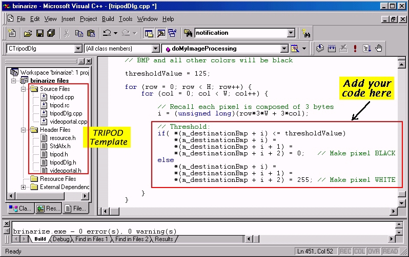
ANSI C/C++ programmers will recognize that in doMyImageProcessing,
the code nested between the two for loops is ANSI C.
m_destinationBmp is a pointer to an array of pixels and
*(m_destinationBmp + i) is the value of the i'th pixel. The two
for loops will allow you read, process and write each pixel. After
cycling through the array, a final m_destinationBmp results and
can be displayed. doMyImageProcessing and displaying m_destinatiomBmp
runs in real-time (30 frames/sec) if the nested code is not computationally
intensive (like simple threshold calculations),
m_destinationBmp points to a 24-bit grayscale bitmap. It is
320 pixels wide by 240 pixels high. It is malloc'ed and created in the function
grayScaleTheFrameData. In this function, sourceBmp points
to the actual pixel data in the 24-bit RGB color image captured by your Logitech
camera. Being RGB, each pixel in sourceBmp is represented by
three bytes (red, green and blue).
The reason for creating m_destinationBmp is that often, machine
vision developpers use grayscale images to reduce computation cost. If you
need color data, then just use sourceBmp.

An image is an arranged set of pixels. A 2-dimensional array like
myImage[r,c] where r and c are the pixel's row and
column positions respectively, is an intuitive arrangement as illustrated
in the above figure (left). For example, myImage is a (3x4) image
having three rows and four columns. myImage[2,1], which refers to
the pixel at row 2 column 1, has a pixel intensity value "J".
An alternative arrangment, often encountered in machine vision, is the row-column
format which uses a 1-dimensional vector and shown in the figure above (right).
A particular pixel is referenced by:
(myImage + r*W + c)
where myImage is the starting address of the pixels, r and c
are the pixel's row and column positions respectively , and W is the total
number of columns in the image (i.e the image's width in pixels). To access the
pixel's value, one uses the ANSI C de-referencing operator:
*(myImage + r*W + c)
For example for r=2, c=1 and W=4, then
(myImage + r*C + c) yields (myImage + 9). In vector form
myImage[9], which is the same as *(myImage + 9),
has the pixel value "J".
The row-column format has several advantages over the array. First, memory
for an array must be allocated before a program runs. This forces a
programmer to size an array according to the largest possible image the program
might encounter. As such, small images requiring smaller arrays would lead
to wasted memory. Furthermore, passing an array between functions forces
copying it on the stack which again wastes memory and takes time. Pointers
are much more computationally efficient and memory can be malloc'ed
at run-time. Second, once image pixels are arranged in row-column format,
you can access a particular pixel with a single variable, as well as take
advantage of pointer arithmetic e.g. *(pointToImage++). Arrays
take two variables and do not have similar arithmetic operators. For these
two reasons row-column formats are used in machine vision, especially when
more computationally intensive and time-consuming image processing is involved.
- 24-bit Images and Bitmap Image Formats
A 24-bit image uses three bytes to specify a single pixel. Often these bytes
are the pixel's red, green and blue (RGB) contributions. RGB is also known as
the Truecolor format since 16 million different colors are possible
with 24-bits. As mentioned above, m_destinationBmp and
sourceBmp are 24-bit grayscale and Truecolor images respectively.
m_destinationBmp makes all three bytes of a single pixel equal in
intensity value. The intensity is a gray value computed from the amount of
red, green and blue in the pixel. As such:
*(m_destinationBmp + i), *(m_destinationBmp + i + 1), *(m_destinationBmp + i + 2)
are equal (see the function grayScaleTheFrameData if interested).
and is the reason for the code seen in Step 6
above where thresholding set all three bytes to either black or white.
Bitmaps, the default image format of the Windows operating system can
be saved to a disk file and typically have the .BMP extension. Bitmaps can
also exist in memory and be loaded, loaded, displayed and resized.
There are two caveats to using bitmaps. First, pixels are stored from left-to-right
but bottom-to-top; when a bitmap is viewed, pixels towards the bottom are
stored closer the image's starting address. Second, a pixel's color components
are stored in reverse order; the first, second and third bytes are the
amounts of blue, green and red consecutively. Again, grayScaleTheFrameData
function can be referenced to see this reverse-ordering of color.
Code Operation
 The flowchart shows brinarize.exe's function calling sequence.
A Window's application begins with a call to OnInitDialog. Code here
initializes the two videoportal's size. A call to allocateDib allocates
memory to display both the image captured by your Logitech camera and the image
resulting from doMyImageProcessing i.e. binarizing.
The flowchart shows brinarize.exe's function calling sequence.
A Window's application begins with a call to OnInitDialog. Code here
initializes the two videoportal's size. A call to allocateDib allocates
memory to display both the image captured by your Logitech camera and the image
resulting from doMyImageProcessing i.e. binarizing.
The Logitech SDK defines a variable flag called NOTIFICATIONMSG_VIDEOHOOK
and goes true whenever a new image frame is acquired by your Logitech camera.
After OnInitDialog, the code in OnPortalNotificationProcessedview
checks for this flag and executes. Code here, assigns the pointer
lpBitmapPixelData to the frame's pixel data, grayscales the color image,
executes your doMyImageProcessing algorithm and then displays your image
processing results. If your doMyImageProcessing is not computationally
time-consuming, OnPortalNotificationProcessedview will execute at
30 frames/sec.
Displaying the results of your image processing algorithm is handled by
the function displayMyResults. It uses the MFC function
StretchDIBits which stretches a device-independent bitmap image
to fit the videoportal's display window.
Where To Go From Here
This step-by-step tutorial offers a rapid method to develop real-time image
processsing applications in Windows. TRIPOD is a set of files that
serve as a template where you can easily integrate your machine vision
algorithms in ANSI C; a pointer to image pixels and row-column format offered
in the doMyImageProcessing function does not require low-level knowledge
in MFC, VC++, and the Win32 API. A real-time binarization was illustrated
using TRIPOD
Machine vision is fascinating and fun but its implementation often requires
specific programming skills and specialized hardware that obsures
computer vision theory. For example, binarizing images is fundamentally, a
simple concept. TRIPOD's files and the Logitech's Videoportal ActiveX
component takes care of the low-level issues like acquring frame data, processing
pixels and displaying results. TRIPOD and a Logitech USB camera enable
any developper with ANSI C knowledge to quickly implement real-time computer
vision algorithms.
Binarizing images just served as a "Hello World" introduction to machine vision.
Algorithms like detecting edges and colors, tracking regions and counting objects
can be easily implemented. Handbooks like Myler's The Pocket Handbook
of Image Processing Algorithms in C (ISBN: 0-13-642240-3) provide code for
such applications. Such algorithms can value add your Logitech USB camera with
tasks like surveillance, robot navigation and image recognition.
Future work for this tutorial's author includes additional code examples
like tracking and visual-servoing. Additionally the author hopes to
develop a Visual Basic (VB) version of TRIPOD. VB offers rapid development
of Window GUIs without a steep learning curve.
Review of Existing Machine Vision Software
Ideally machine vision development would focus on generating better algorithms and
formulating theories rather than struggling with low-level software/hardware issues.
For example, algorithms for improved image understanding/recognition or tracking
multiple targets are active research areas. However with many existing Windows-based
packages, implementing these algorithms is frustratingly difficult, oftentimes
demanding specialized DirectX, Win32 API and MFC knowledge. As such, machine vision
researchers and developers can resort to Linux/Unix based platforms to have
more control over low-level details. The reality however is that software/hardware
for Windows-based PC's is more prolific and often affordable. Furthermore end-users
of one's machine vision code, like surveillance and manufacturing companies, will most
likely want a Windows-based version.
Reviewed below are the author's experiences with some existing software/hardware packages
that offer real-time image handling with a Windows PC, where images are grabbed through
a video camera, processed and displayed. Software that only works with static image files
or non-Windows are not reviewed. The review's purpose is for potential developers
to ascertain a package's potential before both investing time and finances. This
author's experiences have been frustrating for a number of reasons and hence TRIPOD
was conceived and developed: (1) Some packages only have canned solutions, forcing
you to use the package's machine vision functions. Often source code is not available
or there's little documentation. As such, the package does not lend itself to developing
one's own algorithms. (2) Some packages require a strong skill set in DirectX, Win32 API
and MFC. Machine vision development demands begin with getting a pointer to the
frame's pixel data and algorithms are then a matter of processing pixels. The pre-requisite
skill set however makes implementation frustratingly time-consuming especially since
there are few books on DirectX programming dedicated to processing video.
(3) Some packages have run-time licenses where distributing your machine vision
solutions forced purchasing additional licenses.
Free or Low-Cost Packages
This open-source computer vision software library is a beautiful offering and
has a dedicated user group. Frustrating however is that it has compile bugs,
code is not well-documented and some examples rely on compiled object code
or DirectX. Those comfortable with DirectX, MFC and Win32 API can perhaps
debug and develop applications. Those without such experience will find the
learning curve very steep.
With Logitech's ActiveX component and the accompanying manuals one
can quickly develop a VB, VC++ or Win32 API application to display real-time
video captured by a Logitech USB camera. The manuals explain how to display
video acquired by the camera, record video to an AVI file, take snapshots
and add text to displays. The Vidbert example source code can be studied to
understand how to get a pointer to the frame's image data. Unfortunately the code
is not well documented nor is Vidbert's operation explained in the manuals and
it does not arrange pixels in a standard row-column format. The ActiveX component
is free and has no run-time licenses. The QCSDK has a lot of potential as this
tutorial has shown. James Matthews gives a nice programming
tutorial as
well as a motion
detection example.
The free download is an executable that demos some applications created with
their ActiveX component. Not all the demos work. The commercial version (apx.
$149 USD) offers some canned Visual Basic functions like negation and motion
detection. Accessing the actual pixel data is not available however. Calling
the Technical Help desk did not resolve questions about the non-working demos, pixel data
access and compile failures. As such, this package is not really for developers who wish to
design their own real-time processing algorithms. It however can give VB programmers a
quick way to display video captured by a Logitech Quickcam camera. However, Logitech's
SDK provides the same functionality for free.
The 14-day free trial OCX (ActiveX) component has potential for real-time
image processing with USB and Video For Windows (VFW) compatiable cameras
and framegrabbers. The commerical version is priced at $99.95 USD ($39.95 USD student
version). There are several examples but little documentation. The help file does suggest
a pointer to the image frame's pixel data is available. Furthermore, it appears
that programmers skilled in MFC might make use of this OCX.
Pong Suvan has a number of nice programs for machine vision. The executables
demonstrate some canned processing examples like Sobel filters and blob analysis.
He gives some explanations on using his software to develop image processing
applications but not in enough detail for non-MFC programmers. Pong frankly
states that he cannot give the full source code. As such, it isn't clear
exactly how to access the frame's pixel data.
Research Lab Level Packages
The two packages below are relatively expensive and require a separate (CCD) camera purchase.
Coreco is a machine vision hardware/software OEM. $3600 buys one a single license for Sherlock
which only runs on their framegrabber line. Any code that may be distributed requires purchasing
additional licenses. The PCVision framegrabber costs $1250 USD. Additionally, once the
software is installed in a PC, it cannot be re-installed on another PC. This author bought the
package as a potential development platform for his research students. Although the software's
ActiveX component has canned solutions like blob analysis, region-based tracking and optical
character recognition, it sadly does not allow one to easily custom programming. Also
the algorithms are sadly 2D and perhaps one or two generations behind what's available in
research labs. As such, it is not well suited as a machine vision research development platform.
Sherlock's market is more geared to manufacturers wishing for a turnkey parts inspection solution.
The $2500 USD (educational discount) Matrox Imaging Library (MIL) and $595 USD Meteor II
framegrabber are well-suited for machine vision development. It does require run-time
licenses but MIL programming is very straight-forward with comprehensive manuals. Developers
with ANSI C knowledge can quickly begin developing code.
Review Conclusions
TRIPOD was created to impact the largest audience namely those interested in machine
vision and know ANSI C. TRIPOD's hardware demands are modest (Win98 233 MHz minimum,
128 MB RAM) and affordable ($50 USD Logitech USB camera). Non-research lab machine vision
developers may find Matrox's MIL too expensive. Also, equipping classroom PCs with Matrox's MIL
is financially out of reach of most schools. This prevents professors exposing course students
to real-time image processing experiences. The $50 Logitech USB camera however
is less than most textbook prices. Every student could potentially buy one and do course
exercises and projects at home. Projects could include tracking, motion detection, optical character
recognition, structure-from-motion, visual-servoing and disparity/stereo. If TRIPOD is used
then professors can focus on teaching the fundamental machine vision theory and
ANSI C would be the only pre-requisite. Professors would not have to tangent off with
DirectX, ActiveX, Win32 API and MFC lectures. This author intends to introduce
an undergraduate/graduate machine vision course with student homeworks and projects implemented
using TRIPOD. Pedagogic experiences will be shared in the future.
Author Information
TRIPOD and tutorial were developed by Paul Y. Oh, a robotics professor
in the mechanical engineering department of Drexel University in Philadelphia,
PA, USA. Prof. Oh's research interests
include visual-servoing,
robotics, mechatronics and 3D reconstruction
of urban areas from aerial photos. Prof. Oh's technical publications can be found in the
IEEE Robotics and Automation proceedings and transactions or
downloaded.
Special Notes for Win2K and WinXP Installation 
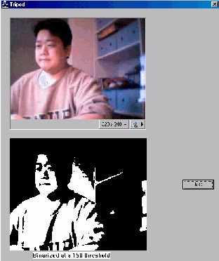 The left figure is an image grab of a Windows application programmed
using TRIPOD. The top viewport (color) displays in real-time,
images captured by a Logitech USB camera's. At the same time the
bottom viewport displays image processing results, in this case, a
binary image (black and white) thresheld at a 150 8-bit grayscale
intensity.
The left figure is an image grab of a Windows application programmed
using TRIPOD. The top viewport (color) displays in real-time,
images captured by a Logitech USB camera's. At the same time the
bottom viewport displays image processing results, in this case, a
binary image (black and white) thresheld at a 150 8-bit grayscale
intensity.